Quantum Hall Effect
In 1985 Klaus von Klitzing won the Nobel Prize for discovery of the quantised Hall effect. The previous Nobel prize awarded in the area of semiconductor physics was to Bardeen, Shockley and Brattain for invention of the transistor. Everyone knows how important transistors are in all walks of life, but why is a quantised Hall effect significant?
Over 100 years ago E.H. Hall discovered that when a magnetic
field is applied perpendicular to the direction of a current flowing through a
metal a voltage is developed in the third perpendicular direction. This is well
understood and is due to the charge carriers within the current being deflected
towards the edge of the sample by the magentic field. Equilibrium is achieved
when the magnetic force is balanced by the electrostatic force from the build
up of charge at the edge. This happens when Ey = vxBz .The Hall coefficient is defined as RH = Ey
/Bzjx and since the current density is jx = vxNq , RH =1/Nq in the case of a
single species of charge carrier. RH can thus be measured to find N the density
of carriers in the material. Often this transverse voltage is measured at fixed
current and the Hall resistance recorded. It can easily be seen that this Hall
resistance increases linearly with magnetic field. 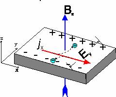
In a two-dimensional metal or semiconductor the Hall effect is also observed, but at low temperatures a series of steps appear in the Hall resistance as a function of magnetic field instead of the monotonic increase. What is more, these steps occur at incredibly precise values of resistance which are the same no matter what sample is investigated. The resistance is quantised in units of h/e2 divided by an integer. This is the QUANTUM HALL EFFECT.
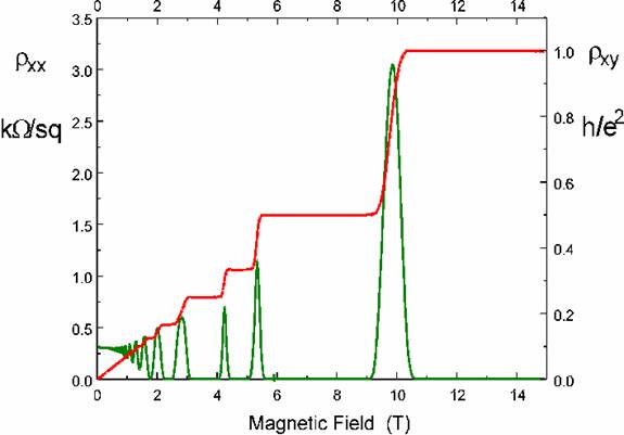 The figure shows the integer quantum Hall effect
in a GaAs-GaAlAs heterojunction, recorded at 30mK. The QHE can be seen at
liquid helium temperatures, but in the millikelvin regime the plateaux are much
wider. Also included is the diagonal component of resistivity, which shows
regions of zero resistance corresponding to each QHE plateau. In this figure
the plateau index is, from top right, 1, 2, 3, 4, 6, 8. Odd integers
correspond to the Fermi energy being in a spin gap and even integers to an
orbital LL gap. As the spin splitting is small compared to LL gaps, the odd
integer plateaux are only seen at the highest magnetic fields. Important points
to note are:
The figure shows the integer quantum Hall effect
in a GaAs-GaAlAs heterojunction, recorded at 30mK. The QHE can be seen at
liquid helium temperatures, but in the millikelvin regime the plateaux are much
wider. Also included is the diagonal component of resistivity, which shows
regions of zero resistance corresponding to each QHE plateau. In this figure
the plateau index is, from top right, 1, 2, 3, 4, 6, 8. Odd integers
correspond to the Fermi energy being in a spin gap and even integers to an
orbital LL gap. As the spin splitting is small compared to LL gaps, the odd
integer plateaux are only seen at the highest magnetic fields. Important points
to note are:
The value of resistance only depends on the fundamental constants of physics:
e the electric charge and h Plank's constant.
It is accurate to 1 part in 100,000,000.
The QHE can be used as primary a resistance standard, although 1 klitzing is a little large at 25,813 ohm!
Explanation of the Quantum Hall Effect
 The zeros and plateaux in the two components
of the resistivity tensor are intimately connected and both can be understood
in terms of the Landau levels (LLs) formed in a magnetic field.
The zeros and plateaux in the two components
of the resistivity tensor are intimately connected and both can be understood
in terms of the Landau levels (LLs) formed in a magnetic field.
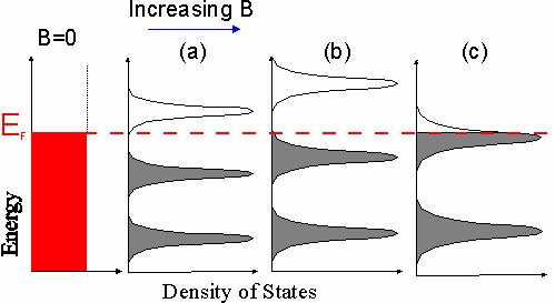
In the absence of magnetic field the density of states in 2D is constant as a function of energy, but in field the available states clump into Landau levels separated by the cyclotron energy, with regions of energy between the LLs where there are no allowed states. As the magnetic field is swept the LLs move relative to the Fermi energy.
When the Fermi energy lies in a gap between LLs electrons can not move to new states and so there is no scattering. Thus the transport is dissipationless and the resistance falls to zero.
The classical Hall resistance was just given by B/Ne. However, the number of current carrying states in each LL is eB/h, so when there are i LLs at energies below the Fermi energy completely filled with ieB/h electrons, the Hall resistance is h/ie2. At integer filling factor this is exactly the same as the classical case.
The difference in the QHE is that the Hall resistance can not change from the quantised value for the whole time the Fermi energy is in a gap, i.e between the fields (a) and (b) in the diagram, and so a plateau results. Only when case (c) is reached, with the Fermi energy in the Landau level, can the Hall voltage change and a finite value of resistance appear.
This picture has assumed a fixed Fermi energy, i.e fixed carrier density, and a changing magnetic field. The QHE can also be observed by fixing the magnetic field and varying the carrier density, for instance by sweeping a surface gate.
Dirt and disorder
Although it might be thought that a perfect crystal would give the strongest effect, the QHE actually relies on the presence of dirt in the samples. The effect of dirt and disorder can best be though of as creating a background potential landscape, with hills and valleys, in which the electrons move. At low temperature each electron trajectory can be drawn as a contour in the landscape. Most of these contours encircle hills or valleys so do not transfer an electron from one side of the sample to another, they are localised states. A few states (just one at T=0) in the middle of each LL will be extented across the sample and carry the current. At higher temperatures the electrons have more energy so more states become delocalised and the width of extended states increases.
The gap in the density of states that gives rise to QHE plateaux is the gap between extended states. Thus at lower temperatures and in dirtier samples the plateaus are wider. In the highest mobility semiconductor heterojunctions the plateaux are much narrower.
Some Interesting Variants on the QHE
In very high mobility samples extra plateaux appear between the regular quantum Hall plateaux, at resistances given by h/e2 divided by a rational fraction p/q instead of an integer. This is the fractional quantum Hall effect (FQHE). Early observations found that q was always an odd number and that certain fractions gave rise to much stronger features than others. The FQHE is much more difficult to explain since it originates from many electron correlations, but for this reason has been of great interst to theoreticians and experimentallists alike.
In some materials there are more than one species of charge carrier. These may be elecrons in different conduction band minima, different spatially confined subbands or electrons and holes simultaneously present. The numbers and mobilities of all the species have to be considered to find the transport coefficients.
If there are electrons and holes the total filling factor is the difference between the filling factors for electrons and holes. At certain fields this can be zero, at which point the Hall resistance itself becomes zero!
